These days, manufacturers of all sizes are taking a closer at their energy consumption as a potential source of cost savings — even manufacturers of the largest, most expensive products in the world.
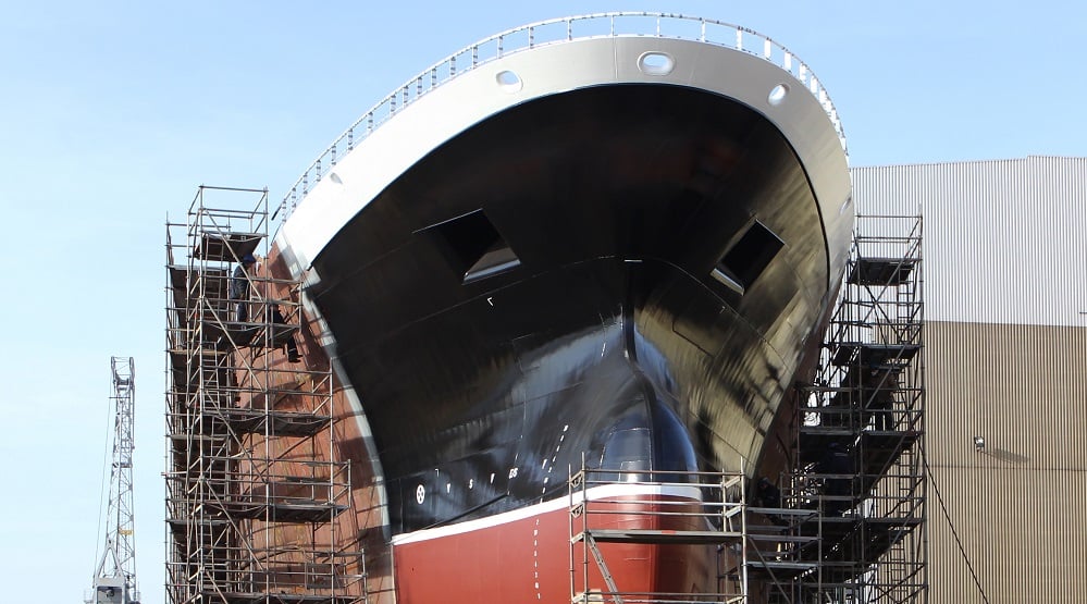
The Marine Industry is no different. A huge 11,000-tonne section of one of the Royal Navy’s under-construction aircraft carriers has been moved out of BAE Systems dock hall for the first time.
The largest section of HMS Prince of Wales was driven out of the hall this week at the Govan shipyard at 1 mph using nearly 2000 wheels and a single remote control.
The ship builder who builds aircraft carriers and other warships for the Royal Navy said one project can cost upwards of £6 billion, but that doesn’t stop the defence giants from examining the cost of installing one of the smallest and lowest tech parts on the boat: the studs, pins, brackets and other fasteners welded to frames, walls and bulkheads.
One Navy ship can contain millions of these welded fasteners. So ship builders and stud welding equipment manufacturers teamed up to quantify how much energy they could save by swapping out their old stud welding equipment for newer, more energy-efficient models.
Inverters vs. Rectifiers
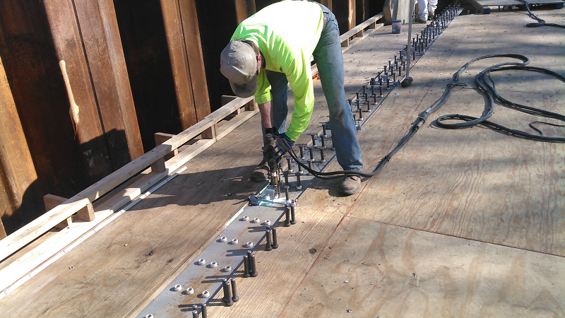
Stud welding is a process by which a metal stud is joined to a metal workpiece by heating both parts with an arc of electricity. The workpiece need only be accessible from one side.
A variety of fasteners can be welded with this method, including threaded studs, pins, tabs, tapped sockets, hooks, loops, brackets, hydraulic fittings, and special hardware adapted to a specific task, such as securing hoses or wire harnesses.
The technology is used in myriad industries and applications. In the automotive industry, for example, it’s used on heat shields, power steering assemblies, exhaust systems and other components. It’s also used on aerospace assemblies, tractors, commercial dishwashers, office furniture, air conditioners, barbecue grills and cookware.

There are two basic technologies for stud welding: drawn arc and capacitor discharge.
The drawn arc technique requires a DC power supply to create the arc, a weld gun, and a disposable ceramic ferrule, which concentrates the heat and contains the molten pool of metal. The stud is loaded into the gun’s chuck and a ferrule is placed over the end. The gun is then placed against the workpiece.
When the trigger is pulled, the power supply sends a signal that energizes the gun’s internal lift mechanism, lifting the stud and drawing a pilot arc. This arc establishes a path for the weld current, which follows immediately after.
After enough arcing time, a weld pool forms and the lift mechanism is de-energized. This causes the stud to plunge into the molten metal. As the stud and the base metal join, the metal cools and the weld is formed. Flux embedded in the stud vaporizes during the operation to keep the weld zone clean.
The capacitor discharge technique requires a weld gun and a capacitor storage system to produce a rapid electrical discharge. Ferrules and flux are not needed, but the stud must have a special projection on the end to be welded.
There are two techniques for capacitor discharge welding: contact and gap. In contact welding, the stud is loaded into the gun and positioned in contact with the workpiece. Energy is then instantaneously discharged from the capacitors through the stud’s projection. The projection vaporizes, creating a gap that allows an arc to be formed. As the stud and workpiece begin to melt, they are forced together, and the weld is produced. In gap welding, the stud is positioned above the workpiece rather than on it.
Capacitor discharge is a very quick process. With arc welding, you can have weld times from 50 milliseconds to 1.5 seconds. Penetration into the base material could be as high as 0.125 inch.
Capacitor discharge is best for applications requiring a cosmetic appearance.
Drawn arc welding is more for structural applications.
Improving Quality, Productivity
Aside from better power supplies, improvements in stud welding technology have been mostly incremental. Lighter weight, servo-driven weld heads are facilitating automated welding applications. Microprocessor control is enabling engineers to set and monitor process variables such as current, voltage and time. Changes in the amount of energy consumed during a weld could indicate a bad assembly.
Some suppliers now offer equipment that can run more than one weld gun. That enables one power supply to serve more than one welding station, or it allows one station to be equipped with multiple guns. For example, one gun could be reserved for 1/4-inch fasteners while another could be set up for 5/8-inch fasteners. That saves setup time.
Changing over a chuck is only a 5-minute chore, but if you do that 10 to 15 times a day, you can lose more than an hour of production.
Since the first all-welded ship was built in 1919, the global shipbuilding and offshore sectors have been the largest and most demanding across the range of welding equipment.
HAVE YOU CONSIDERED UPGRADING YOUR MACHINE TO A NEWER MODEL?
Specialising in heavy duty welding and cutting equipment, we can supply the whole range of used and refurbished machinery needed for the Ship building and offshore industries.
- Stud welders
- Automatic Submerged arc welding equipment
- Hand-welding MIG/MAG welding machines
- Machines for gas, plasma and laser cutting
- Specialized equipment, narrow-gap welding machines and orbital TIG welding heads


comments
Thanks for sharing all of this information about stud welding in the marine industry. I had no idea that this type of welding involved heating both sides of the metal to fasten another piece on. If you can only access the metal from one side, then the welding guns must be pretty powerful to heat up both sides of it!